Sape
-
Posts
5 -
Joined
-
Last visited
Sape's Achievements
")


-
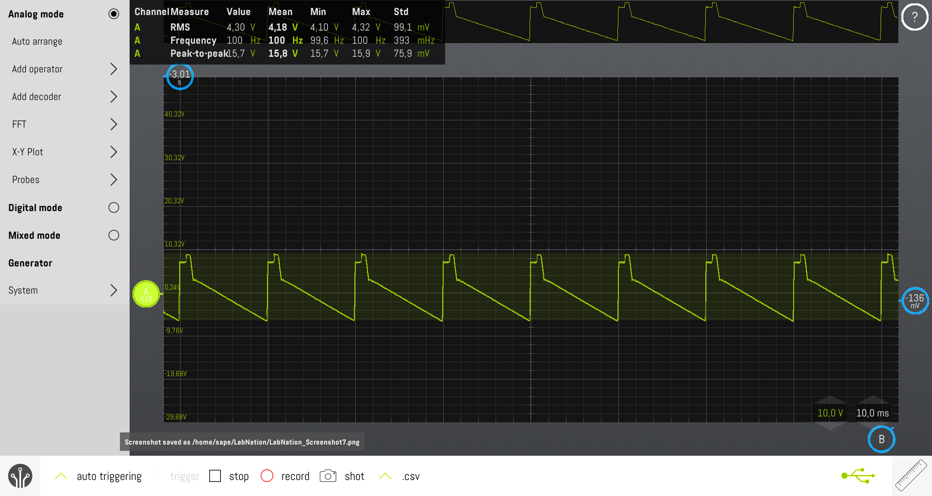
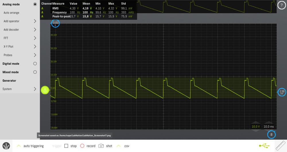
Kevin, Edward, Thanks for the support and the schematic. I was a bit of a puzzle to get access to the file, but I managed. Anyway, your help is amazing. Back at home, I cannot tell you the PCB part number and version. I do remember seeing 1988 printed on them. Indeed for 50Hz UK, K3 is fitted, K2 is not fitted. Same for the Netherlands 😀 The ramp signal is present on IC1 pins 1,5,9,13 if you wanted to check that now you have updated service information..... Yes, it was pure luck we found this signal on IC1 pin 1. See attached. The cable will act as a low pass filter, will pick up a lot of electrical noise... My best guess is there are 24-core (or at least 17 cores if a common earth wire is being used) cables from dimmer outlets to each aluminum tube with 8 outlet sockets in the grid, length probably 20 meter each. Also, for load distribution purposes, each cable is connected to different dimmer units, which on their turn can run on different power supply phases. So there is a mix of AC currents going up and down that will influence each other indeed. Sounds like there is an issue with the ramp generator circuit. When you say LEDs above,..... I meant indeed L1 and L2. For 17 preheat adjustments I was able to find the setting that the theater lights and L1, L2 were at the edge of illumination simultaneously. For number 18 this was not possible. L3 was always on, on all units. The LM324 are soldered, not easy to replace. Anyway, the schematic provides sufficient inspiration to check various signals simultaneously like IC1 pin 10 & 12, IC1 pin 8 & 14, IC3 pin 2 & IC4 pin2 and Q1 & Q2 collectors. Interesting to see L1 and L2 are now in series with the optocoupler LED's. Once again, thank you very much for your help. We can figure it out now, after the holidays.

-
Hello Kevin, Last Saturday we opened one unit that had dimmers with expected curves as well as weird curves and did some testing on these. We first did the adjustment of the preheat. They were all off by far, so once corrected, the faders gave a much better linear control of the intensity. The weird oscilloscope images remained the same at partial loads. The unit was connected to a single phase 230V which makes sense as the lamps are also 230V. The whole rack containing 6 units is fed with 3 phases + neutral, so my best guess is that each 2 units share a phase. The frequency settings were OK @ 50Hz. The big capacitors looked fine by appearance, no swollen end caps that indicate a problem. Unfortunately the PCB layout differs considerably from the circuit diagram I posted earlier. Doing checks on the board is not easy as there are many thick wires going across that limit access to the components. Nevertheless I was able to pick up a signal from the LHS opamp at pin #1 (AFAIK) that resembled pretty much the signal shown in the diagram at the test point. We were not able to find the other signal shown on the diagram, so we skipped that. We then checked the output of triacs. These were all absolutely fine for 25, 50, 75 and 100% DMX input! But still, at the socket, near the lamp, the signals were still weird. I must admit we used a 10 m hedge cutter cord to floor level in order to connect the oscilloscope. Our preliminary conclusion is that the wiring to the grid can cause the problem. In the grid, we have 6 aluminum tubes containing 8 individual sockets each that are wired with long multi-core cables to big Harting connectors in the back of the dimmer rack. Question to you: Are there any recommendations for the wiring, like twisted pairs or shielded? Anyway, the controlability has improved a lot thanks to the preheat adjustment, so we leave it for the moment. There was one other issue we faced: on the third dimmer set of another unit we were not able to make a synced preheat adjustment for both channels. This was both visible at the control LED's as well as at the lamps themselves. Do you have any suggestion to solve this? For the time being we discontinued the use of this channel.
-
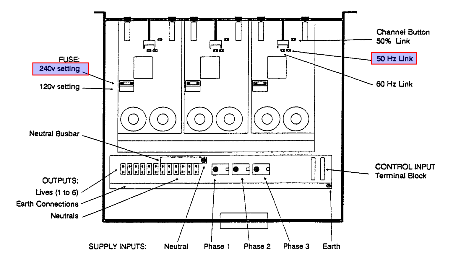
Hello Kevin, Thanks for reply again. I included the circuit diagram which I found in a Rackmaster 660 service manual, but interestingly this print also lists model 260. However, AFAIK the 260 cannot run on a 0-4.3 mA input signal, so may I assume that components related to this input are left out? The inductor you referred to is probably shown as filter in this diagram. Correct? Studying simple household dimmer circuits I do not find these coils. In the diagram I cannot find an adjustable component related to the pre-heat function. Am I overlooking something? Next Saturday we will take one or more unit apart and do some measurement. I suggest checking the multi-exchanger's 0-10V output as a starting point, the TP test point, the point between IC2 and C8 (at least the diagram shows what to expect here), the diac's LED, its input and output. It could well be that the 6 units are too tight in the rack so that components suffered from the heat. I also suspect the units haven't been opened since the start of their operation, so we expect to find a lot of dust. I let you know the outcome. Sape zero88_rackmaster_schema.pdf
-
Dear kgallen, Thanks for your reply. Reading your comments, I checked my measurement notes. Due to time constraints we could not test all 36 channels. On one unit, signals from 1/2 were nice, 3/4 and 5/6 were weird. However on two other units, 3 was nice while 4 was weird and 5 was nice while 6 was weird. So these results do not clearly point the finger to the control side. From what I learned about dimmers is that the triac cuts away a part of the sinus. The remainder should still match more or less the original AC sinus. And that is clearly not the case. Just found a circuit diagram for Rackmaster 260/660. Needs a little closer investigation. It'll take a while, but I'll certainly come back on this topic.
-
Sape joined the community
-
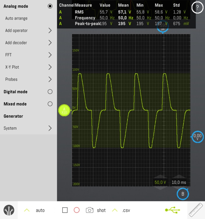
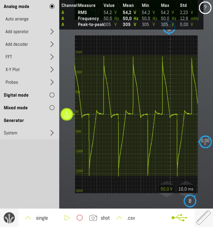
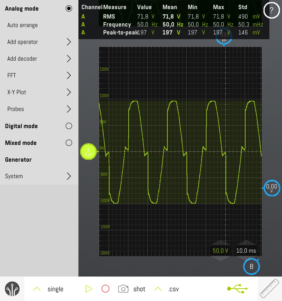
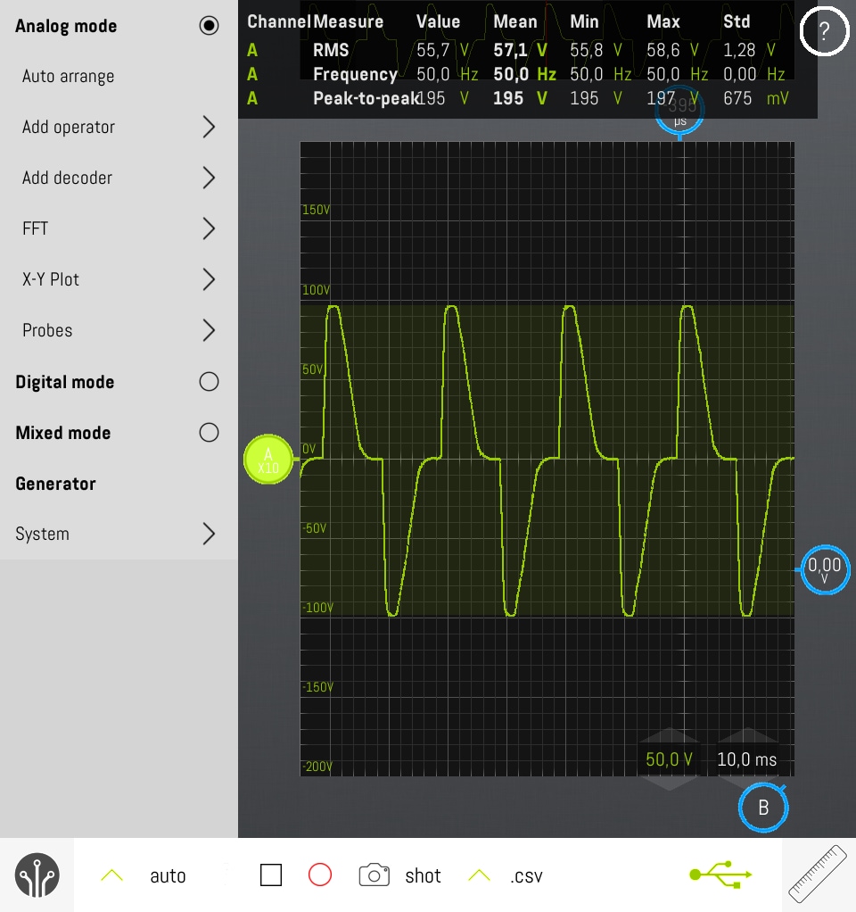
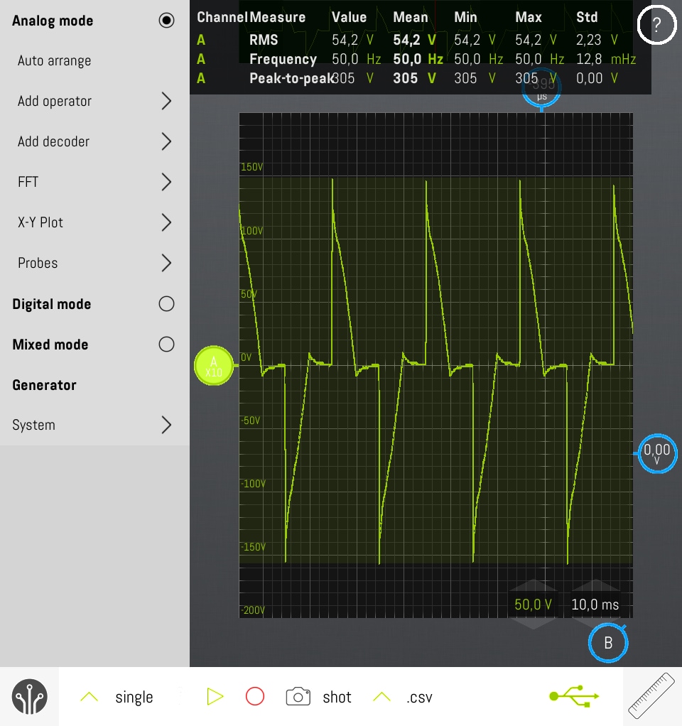
Just read this topic with great interest. As a volunteer technician in our theater we have a similar problem. If we control 4 identical lights simultaneously, their intensity differs considerably at partial load. We have 6 Rackmasters 260 connected to a Showtec Multi-exchanger and a number of halogen lights ranging from 500 to 2000W per channel. I haven´t tried to adjust the preheat, that will definitely be a next step. The reason of my response: last week we analyzed the output with an oscilloscope and found weird curves. At 50% DMX signal many channels had no output at all. We hope/expect to improve this with preheat adjustment. At 75% we actually saw two different patterns: one decent,typical, leading edge dimmer curve, and another one jumping up and down to high peaks with a peak-to-peak voltage of 915V, considerably higher than about 615V from the power supply. The 100% curve was more or less as expected. My question: what could be the reason for this different behavior @75%? Could it be dried up capacitors mentioned in the latest response? A few comments: In all cases we used the same 1000W lamp. For safety reasons, the oscilloscope signal was connected via a voltage divider consisting of 3x 10k resistors so you have to multiply the voltages in attached images by 3. We haven´t opened a unit yet, that will also be a next step. Your reply is highly appreciated.